
Fabless mixed-signal SoCs · Designed in Australia
Sample at the rate the information needs.
Not the rate the worst case needs. We're designing self-calibrating adaptive ADC systems-on-chip for AI data-centre power: quiet while the signal is quiet, full detail the moment something starts, and a hardware decision before software even hears about it.
The first principle
A fixed-rate ADC pays for the worst case, all the time.
Every sensor in a data centre ends at an analog-to-digital converter. How that converter decides when to sample sets the cost of everything downstream of it.
-
Sensors turn the physical world into numbers.
An ADC measures a signal at fixed intervals. Every measurement becomes data that has to be sent, processed and stored.
-
The sampling rate is set by the worst case.
To capture a signal faithfully, you have to sample faster than its quickest change (the Nyquist criterion). A fixed-rate ADC can't know when that change will come, so it runs at top speed all the time.
-
Most of the time, nothing is happening.
Voltage sits at nominal, temperature drifts slowly, current is steady. Sampling a flat signal at full speed produces a stream of values that repeat what you already knew — a lot of data, very little information.
-
Every sample has a cost further down the line.
Each one is converted (ADC power), sent (network bandwidth), processed (CPU) and stored (SSD). Removing a redundant sample at the sensor saves all of them at once.
-
So make the data track the information.
The adaptive ADC watches the signal in hardware. When it's quiet, it samples slowly. When it sees early signs of an event — a rising rate of change, harmonics building, a crossed threshold — it jumps to a high sampling rate and wider bandwidth. A small pre-trigger buffer keeps the moments before the switch, so the start of the event isn't lost. Once things settle, it slows back down.
-
Less data can also mean faster data.
On links where bandwidth is genuinely limited — remote sites, wireless, satellite — less routine traffic means the data that matters, the event itself, arrives with less queuing delay. The system gets less data and faster data at the same time.
-
Battery charge estimates stay honest.
Battery charge is estimated by adding up current over time (coulomb counting). A slow fixed-rate ADC misses or blurs short current spikes, so the running total drifts. The adaptive ADC samples fast during those spikes, keeping the estimate accurate without paying for high-speed sampling all day.
Slow drift — offset, capacity fade — still needs separate compensation.
 Photo: BalticServers.com · CC BY-SA
What it solves
The problems, ranked by evidence.
We rank each problem by the public evidence behind it, and say plainly where the link to our chip is indirect. The strongest problems lead; the weaker ones stay in as context, labelled as such.
Power telemetry is too slow for AI load swings.
AI training makes huge fleets of GPUs change power together, so a whole facility's draw oscillates — and grid operators need to see those swings quickly. Reference GPU telemetry pipelines report averaged power far more slowly than that, and even vendor developer forums can't say what the true sensor refresh rate is.
The stakes are already visible. In a documented Virginia grid disturbance, a large block of load that operators hadn't anticipated dropped offline at once; NERC found it was exclusively data-centre-type load. NVIDIA has since built energy storage into its rack power shelves to smooth the peaks the grid sees. Operators are spending money on this problem.
Sensor energy is wasted on redundant samples.
At a fixed resolution, ADC power rises in step with sample rate. In wireless sensor nodes the radio costs far more than the sensing itself, so every sample you don't send is energy you keep. Measured adaptive-converter designs in the research literature cut conversion work, power and data substantially.
Matters most for wearables, wireless industrial sensors and structural monitoring — little for mains-powered data-centre meters.
Full-waveform detail is unaffordable, so it gets thrown away.
Waveform-level power monitoring runs at high sample rates. Keeping that detail continuously would cost petabyte-scale storage per site, so nobody keeps it: operators store compressed summaries and stay blind to fast events.
Industry practice already uses tiered averaging windows and pre-trigger event buffers, and published compression methods shrink power-quality data a great deal. No study yet compares an adaptive-rate ADC directly against continuous capture — a gap we intend to fill with our own data.
Fixed-rate meters miss fast transients.
Commercial power-quality meters take a fixed number of samples per mains cycle. A standard lightning-type impulse slips straight between them; catching transients reliably takes megasample-class rates. Running that fast all the time multiplies both data and power.
Battery state-of-charge drifts because current spikes are missed.
Coulomb counting accumulates error. Peer-reviewed work names current-integration approximation error — sampling too slowly for how fast current changes — as a distinct error source, and vendor application notes show fast current content being filtered out of the fuel gauge entirely.
Why data centres care: lithium-ion is a growing share of UPS installations, and battery-management readings increasingly replace physical checks.
Adaptive sampling fixes the fast-spike part. Slow drift still needs separate compensation.
Observability cost and alert overload.
Observability takes a meaningful slice of infrastructure spend, cost ranks as a top priority for most teams, and alert fatigue is the leading obstacle to fast incident response.
Honest link: this is mostly IT data. We reduce only the physical and power-telemetry share.
Staffing, and the push toward AI operations.
Hiring for data-centre operations keeps getting harder, and staffing is a top operations concern in industry surveys. That pressure is pushing operators toward AI-assisted operations.
We don't claim to solve staffing.
Power-limited campuses strand capacity.
AI campuses limited by their grid connection hold capacity in reserve so breakers never trip. But the breaker sees the total of every GPU behind it — one GPU's reading can't tell you how close a row is to tripping, so the reserve stays wide.
Software is too slow to stop a trip.
When software sits between detecting a problem and reacting to it, the time and energy lost in that gap is what does the damage. Solid-state switches are fast; the decision path in front of them isn't.
Drifting sensors eat the margin.
Readings that drift with time and temperature force operators to keep wide safety margins — capacity paid for and never used.
Synchronised training can shake the grid.
Researchers from Microsoft, OpenAI and NVIDIA warn that training swings GPU fleets between near-peak and near-idle power together — and that if the frequency content of those swings lines up with critical frequencies of the grid, it can damage grid infrastructure.
Slow degradation hides under every threshold.
Harmonic distortion that creeps up a little each day never crosses an event trigger — which is exactly the objection a sceptic raises against event-based capture.
Fast failures can't be reproduced.
A droop or a ringing event is over long before an averaged reading updates. With nothing captured, the debug loop ends in a permanent workaround — raise the voltage, lower the clocks — paid for over the life of the platform.
That facility sensors fill SSDs with petabytes today — the real point is that full detail would cost that much, so it's discarded. That the chip "predicts" events — it detects them early. Or that it relieves data-centre network congestion — only links that are genuinely bandwidth-limited. Global data-volume headlines describe all data everywhere, not sensor data, so we don't use them as evidence.
Two ideas · one core
Two chips built on one self-calibrating adaptive ADC.
The same converter core serves both. What changes is where the chip sits in the power path, and what it decides once it sees an event.
 Bermix Studio / Unsplash
Adaptive Telemetry ADC
Data that tracks information — for the sensors watching facility power, racks and servers.
- Sits at
- Facility circuits, rack sensors and server sensors
- Solves
- Slow power telemetry, discarded waveforms, missed transients, battery charge drift
- Decides
- When to sample slowly and when to burst
 Robert Harker · CC BY-SA
Rack Power Guard working name
Run more GPUs on the same power connection — without tripping breakers.
- Sits at
- Rack power shelves, busbars, PDU branch circuits, server power-supply inputs — with an alert wire to the GPUs
- Solves
- Stranded capacity, slow software protection, drifting sensors
- Decides
- When GPUs must throttle to protect the breaker
Shared core: a self-calibrating adaptive ADC that keeps its accuracy while it switches rate and bandwidth. The trigger and buffer stay the same across applications — only what sits on top changes.
Idea one · Adaptive Telemetry ADC
A converter that knows when to pay attention.
It samples slowly while the signal is steady, detects the early signs of an event in hardware, and switches to a high sampling rate and wider bandwidth just as the event begins. A pre-trigger buffer keeps the leading edge; a low-rate baseline stream never switches off.
Because the decision happens at the moment of conversion, a redundant sample is never created — so it never costs converter power, network bandwidth, CPU or storage.
Analog front end
Conditions the sensor signal before conversion. Its bandwidth opens when an event needs it and narrows when the signal is quiet, so noise isn't converted for nothing.
Adaptive SAR ADC G&G IP
The converter itself. It changes sampling rate and bandwidth on demand, instead of running at the worst-case rate all the time.
Background calibration engine G&G IP
Keeps accuracy while the converter switches modes, correcting the settling and bandwidth-mismatch errors that normally appear when a converter changes speed.
Onset detector G&G IP
Watches for the early signs of an event — a rising rate of change, harmonics building, a crossed threshold — and flags it before the event is fully under way.
Mode controller
Decides between baseline and burst, holds the burst until the signal has genuinely settled, then steps the converter back down.
Pre-trigger buffer
A small memory that keeps the moments just before the switch, so the start of an event is never lost to the time it takes to react.
Report engine
Sends an always-on, low-rate baseline stream — so slow trends are never missed — with full-detail bursts layered on top around events.
Time sync & digital interface
Timestamps readings and delivers them over standard power-management buses, so channels from across a site line up in time.
Idea two · Rack Power Guard
More GPUs on the same grid connection. No tripped breakers.
A power-monitoring system-on-chip for AI server racks, sold with a reference design. It's comparable in size to today's precision power-monitor and energy-metering chips, and built around our self-calibrating adaptive ADC.
It goes where the breakers are — and wires an alert line to the GPUs. That placement is what unlocks the value: the limit being protected is the breaker, and the breaker sees the total of every GPU behind it.
Self-calibrating adaptive ADC G&G IP
Highly accurate voltage and current readings that don't drift over time and temperature — the foundation for running with thin margins.
di/dt onset detector G&G IP
Switches the converter into burst mode at the very start of a power swing, so the swing is measured in full.
Energy accumulator & I²t trip-curve tracker G&G IP
Knows how much thermal budget the breaker has left — breakers trip on accumulated heating, not on a single instant.
Hardware threshold comparators & ALERT pin
Tell the GPUs to throttle within microseconds, with no software in the path.
Headroom register G&G IP
A live "limit minus predicted peak" value that power-capping software reads to decide how much more load a row can take.
Event buffer & adaptive reporting
Sends summaries normally and full waveforms only around events — the data-reduction benefit, built in.
Time sync & PMBus / I3C
Lets readings from hundreds of chips add up across a row, so the total the breaker sees is the total the operator sees.
Self-test & fault flags
Proves the chip is healthy, giving operators the confidence to trust it with thin margins.
The protection loop
All in silicon · no software in the path- Swing beginsGPUs ramp together
- Onset detecteddi/dt crosses the trigger
- Burst capturefull rate, full bandwidth
- Budget updatedI²t trip curve recalculated
- Headroom publishedcapping software sees the margin
- ALERT raisedGPUs throttle within microseconds
- Breaker holdscapacity used, not reserved
A working loop, not just a part
- The chip, designed into rack power shelves, busbars, PDUs and server power supplies.
- A reference design — the board, the alert wiring to the GPU throttle input, and simple capping-controller firmware. Nobody benefits from the chip alone.
- A measured result — rack and row capacity released without breaker trips, shown first on our FPGA demonstrator and then in a pilot.
The makers of rack power equipment
- Power-shelf, PDU and UPS manufacturers, who design the chip into their products.
- Power-component makers that already sell into data centres.
AI campus operators
- Hyperscalers and neoclouds limited by their grid connection.
- They make the case for the chip inside the equipment makers that serve them.
The same core can go further. A GPU-board version, inside the core voltage regulator, would release voltage guardband and load-line margin on each accelerator — but it competes head-on with on-die power management and the regulator makers. We start at the rack, where the value is larger and the space is less crowded.
Where we innovate
Between the GPU and the breaker.
GPU makers already manage power on the GPU itself. Our space is the power path between the GPU and the breaker — and, inside the chip, the moment of conversion, before any data moves.
-
Grid & substation
Where AI load swings are felt, and where operators need to see them.
-
Switchgear, UPS & batteries
Power quality, ride-through events and battery state-of-charge.
-
Row PDU & branch circuits
The breakers whose limits strand capacity.
-
Rack busbar & power shelf
Sees the sum of every GPU in the rack.
-
Server power supply
Input monitoring for each compute tray.
-
GPU board regulator
Voltage guardband and load-line margin.
-
GPU
Manages its own power; throttles on our alert line.
Convert everything, then decide.
Saves storage — but the converter power, front-end bandwidth and reaction time have already been spent.
Decide, then convert.
Saves converter power, front-end bandwidth and reaction latency — and storage too. The on-chip advantage is latency and power, not storage alone.
How we innovate
Adaptive sampling isn't new. Keeping accuracy while it adapts is.
A sceptical investor's first objection is our starting point. Here is what already exists — and exactly what we add to it.
The silicon
What a system-on-chip like ours looks like.
Both chips are mixed-signal SoCs: precision analog, a converter, detection logic and digital interfaces on one die. Below are real dies photographed under a microscope — samples of the class of silicon we design — with our concept blocks mapped on top.
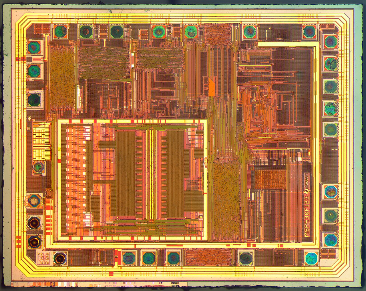 Sample die · not a G&G design
- Analog front end
- Adaptive SAR ADC
- Background calibration engine
- Onset detector
- Pre-trigger buffer
- Report engine & interface
- Reference & bias
- Clock & time sync
- Mode control & self-test
 Sample die · not a G&G design
- Voltage & current sense front end
- Self-calibrating adaptive ADC
- di/dt onset detector
- Energy accumulator & I²t tracker
- Threshold comparators & ALERT pin
- Headroom register
- Event buffer & adaptive reporting
- Time sync, PMBus / I3C, self-test
Reference designs we benchmark against
Every block around our core is a proven SoC pattern. We studied where today's reference parts stop — and put the new work exactly there.
Digital current, voltage & power monitors
Such as Texas Instruments' INA family. Excellent at accumulating energy over time.
Polyphase metering front ends
Such as Analog Devices' ADE family. Accurate power-quality metering with waveform capture.
Coulomb-counting gauges
Integrate current to estimate state-of-charge in battery packs and UPS strings.
Digital multiphase controllers
Report voltage, current and temperature from the regulator over PMBus.
Evidence
What the evidence says — and what it doesn't yet.
We tested the thesis against public research before building anything. Here is each hypothesis and where it landed.
This is a paper architecture. There is no silicon of this design, and no circuit simulation or layout yet. Power, area, accuracy and latency are first-order estimates derived from published comparable parts, not verified for our design. The first proof is an FPGA demonstrator replaying real GPU power traces against an incumbent-style sensor. We'd rather you know that going in.
 Photo: Unnerving duck · CC BY-SA
Beyond the data centre
Anywhere a signal is quiet — until it isn't.
The same adaptive core applies wherever a signal spends most of its life doing nothing, and the rare event is the thing worth catching.
| Application | Quiet state | Event worth catching | What adaptive sampling saves |
|---|---|---|---|
| Power grids & substations | Steady mains waveform | Sags, swells, faults, oscillations | Bandwidth to control centres; full detail when faults happen |
| Solar & wind farms | Steady output | Inverter faults, grid disturbances, ride-through events | Large fleets of inverters multiply telemetry — major data savings |
| Battery storage & EVs | Steady charge or discharge | Current spikes, cell imbalance, thermal-runaway precursors | More accurate state-of-charge; earlier fault warning |
| Medical wearables & implants | Normal rhythm (ECG, EEG, glucose) | Arrhythmia, seizure onset | Battery life — the critical constraint — and a stronger clinical signal |
| Industrial machines | Normal vibration in motors, pumps, turbines | Bearing wear, imbalance, cavitation | Wireless sensor battery life; less cloud storage |
| Buildings & bridges | A still structure | Earthquakes, impacts, crack growth | Years of battery life on sensors that are hard to reach |
| Oil, gas & water pipelines | Steady pressure and flow | Leaks, pressure transients (water hammer) | Traffic on costly satellite or cellular links from remote sites |
| Satellites & space | Nominal subsystems | Anomalies, radiation events | Downlink bandwidth, the scarcest resource on board |
| Automotive | Cruising — radar, battery, powertrain | Emergency events, faults | Less data on in-vehicle networks; lower power |
| Audio & voice devices | Silence | Speech, wake word | Always-on listening at microwatt power |
How we get there
Prove it on FPGA. License the core. Then build the chip.
A path sized for a pre-seed company: every stage produces proof before the next one spends money.
-
Now
FPGA demonstrator
Our ADC model plus the trip-curve, alert and headroom logic, replaying real GPU power traces.
ProofMeasured margin released, against an incumbent-style sensor. -
Next
License the ADC and monitoring IP
To a power-component maker that already sells into data centres.
ProofA first design-in and licence revenue — with no chip-production cost. -
Later
Our own chip and reference design
If the licence partner validates demand.
ProofA pilot rack at an operator.
Team
The team.
The colour here isn't decoration — it's the interference pattern a bare silicon wafer throws off under light. We only let it loose on this section.
Erick Gomez
- MSc in Electrical Engineering; Bachelor's in Mechatronic Engineering
- Analog and mixed-signal IC design, with hands-on tapeout and physical verification
- Speaker at DATE (Design, Automation and Test in Europe); professional experience in the automotive industry
- International experience in South Korea; leadership & business at SolBridge International School of Business
Harshal Giridhar
- University of Sydney; background across biomedical engineering and analog IC design
- Early-stage startup, product strategy and project-management experience
- Runner-up, USRC × SUMO Hackathon; runner-up, Medivate Hackathon
- Translates engineering concepts into customer-focused product
Tushar
- Generative-AI Engineer at AMD, with experience spanning FPGA design and generative AI
- Master of Professional Engineering (Electrical), University of Sydney
- Analog/mixed-signal HDL: Verilog-AMS, Verilog-A, SystemVerilog, VHDL
- Machine learning, deep learning, NLP and computer vision
Hansa Alahakoon
- BE in Computer Engineering, University of Peradeniya; Teaching Assistant, Faculty of Engineering
- Data Scientist (intern) at Dialog Axiata PLC
- Machine learning, deep learning and neural networks; image processing and computer vision
- Python, R, C and JavaScript
The company
A fabless company is a small, concrete step toward sovereign design capability.
The fabless model keeps the high-margin design IP, patents and profits onshore even when wafers are made offshore. Chips are high-value, low-mass exports — designed in Australia and sold into the global data-centre power-semiconductor market.
Sitting close to the largest manufacturing markets in the world, we think Australia can be a credible home for semiconductor design in APAC. That's the long game. Right now, we're at concept stage and focused on pressure-testing the thesis with the people who own the pain.
 Laura Ockel / Unsplash
Get in touch
If power is the bottleneck in your architecture, we'd like to hear how.
A technical discovery conversation
We're at concept stage and want to know whether this problem is real in your architecture — not to pitch a part you can't buy yet. Happy to share the architecture write-up and talk specifics under NDA.
hello@ggsilabs.comCompany details & the thesis
Who we are, the entity and stage, the market thesis, and where the concept currently stands — available on request.
hello@ggsilabs.com